Flange facing is the machining of a flange's gasket seating surface to remove scoring, pitting, corrosion or distortion and restore the flatness and finish the gasket needs to seal. Done on site with a portable flange facer clamped to the flange, it avoids cutting out the spool, shipping it to a workshop and waiting for it to return.
The job turns up wherever bolted joints are opened: refinery shutdowns, heat exchanger and pressure vessel overhauls, pump and turbine casings, offshore piping. The gasket is always the cheap part; the expensive part is a joint that leaks after restart and takes the line back out of service.
What flange facing is and when a flange needs it
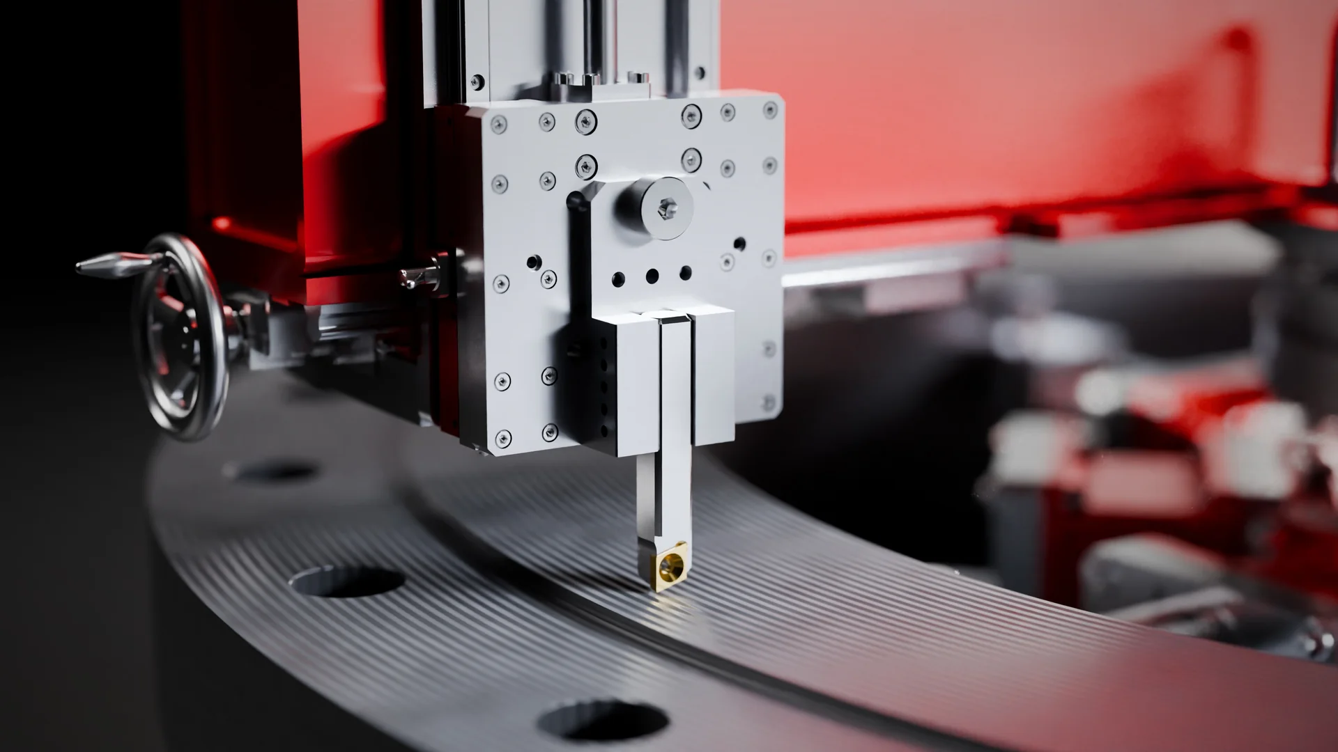
Flange facing (also called flange refacing, flange resurfacing or flange face repair) is a turning operation performed on the sealing face of a flange. A single-point tool travels across the face while orbiting around the flange axis, removing a thin layer of metal until the damage is gone and a new, uniform surface is left. On raised-face flanges the work is on the raised face; on ring-type joint flanges it also concerns the ring groove.
A gasket can only seal what it is pressed against. Any defect that crosses the sealing band, or any area where the gasket cannot be loaded evenly, becomes a leak path. The usual reasons to reface a flange are:
- Radial scoring: scratches running from the bore outwards, left by tools, debris or careless gasket removal. A radial score across the sealing band is the most serious defect, because it opens a direct path from inside to outside.
- Pitting and corrosion: localised attack of the face, common in wet, sour or chemical service and on flanges left unprotected during long outages.
- Erosion: metal washed away by fluid escaping through a joint that has already leaked, typical of steam and high-pressure lines.
- Distortion: faces that are no longer flat because of thermal cycling, welding nearby, uneven bolt loading or knocks during handling.
- Worn or unsuitable finish: serrations flattened by previous gaskets, or a texture that does not suit the gasket type now specified.
Whether a defect is acceptable is not a judgement made by eye. ASME PCC-1, in its Appendix D, gives guidance on flange face flatness and on the size and position of damage that can be tolerated, and most plant procedures build on it. When a defect is outside the limits, facing is the normal repair, as long as enough material remains.
How much metal can come off is a design decision (minimum thickness, flange rating, raised-face height), not a machining one. When the damage is too deep, the face can first be rebuilt by weld deposit and then machined back to size, the same two-step logic described in the guide to weld overlay on worn seats.
On-site flange machining vs the workshop
The traditional route for a damaged flange is to remove the component, send it to a machine shop, face it on a lathe or vertical borer and reinstall it. For a loose valve or a short spool that can work. For a flange welded to a vessel, an exchanger channel or a line that cannot be cut, it is not an option. Even where possible, it carries costs that never appear in the machining quote:
- dismantling, rigging and often cutting and re-welding pipework, with the inspection and testing that follow;
- transport to and from the workshop, plus the time spent in the workshop queue;
- the plant waiting for the part: downtime that usually costs far more than the machining itself;
- reassembly, with new alignment problems.
On-site flange machining reverses the logic: the machine goes to the flange. A portable flange facer is clamped directly on the component in its installed position and the face is machined where it stands, often while other shutdown work carries on around it. It is the same principle behind on-site line boring: take the machining to the part instead of the part to the machine.
Typical cases: line flanges, valves and nozzles during oil & gas and petrochemical shutdowns; heat exchangers, pressure vessels, pumps and turbines in power and process plants; marine and offshore piping. The workshop remains sensible when the part is already off the plant or a spare is on the shelf.
How an orbital flange facer works
A flange facer is a lathe turned inside out. Instead of the part spinning against a fixed tool, the part stays still and the tool orbits around it. Three elements make it work:
- A fixed axis. The machine is clamped to the flange, and the clamping sets the axis of rotation, concentric with the flange.
- A rotating arm. The arm carries the tool holder and turns around that axis, sweeping the tool across the sealing face.
- A radial feed. At every revolution the tool moves a small, constant step along the arm, towards or away from the centre.
Rotation combined with a constant radial feed per revolution traces a continuous spiral across the face. This is the spiral serrated or phonographic finish, named after the groove of a vinyl record. Feed per revolution, insert geometry and the rigidity of the set-up decide the pitch and depth of the spiral, and therefore the roughness of the finished face.
The machine rarely needs to remove much metal; it needs to remove it evenly, in a plane square to the flange axis.
ID mount vs OD mount
Flange facers differ above all in where they take their reference.
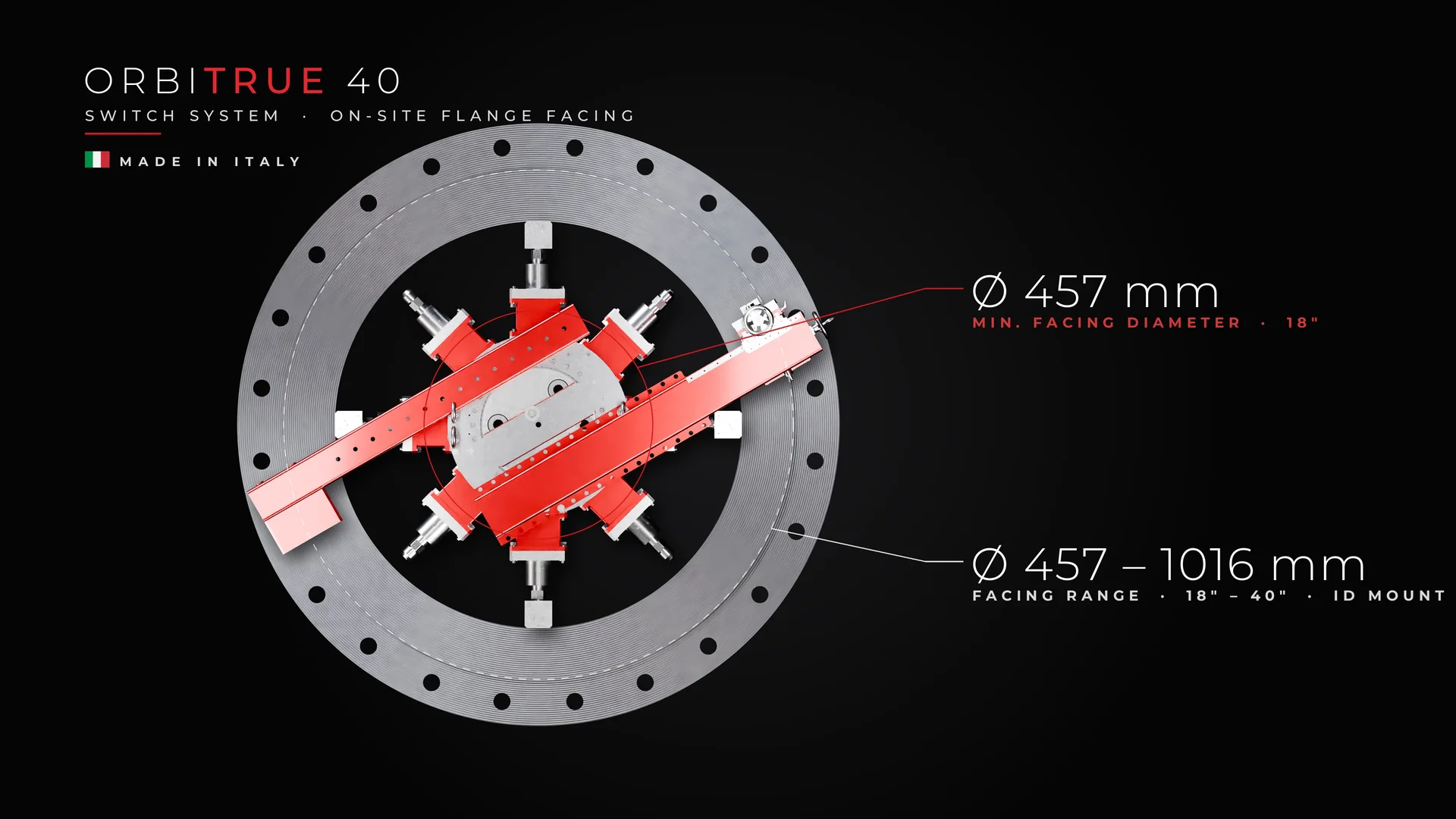
- ID mount (internal mount): the machine clamps inside the flange bore. The bore becomes the axis of rotation, so the machine centres on the flange itself and no external reference has to be built. The set-up is compact and works well in tight spaces.
- OD mount (external mount): the machine is fixed around the outside of the flange, or on a frame that straddles it. It is an approach used where the bore is not accessible, at the cost of more room around the flange and more work to centre the machine.
All Maucotools ORBITRUE flange facing machines are ID mount: the machine clamps in the flange bore, which becomes the axis of rotation, so there is no external reference to set up before cutting.
Flange face finish: what the standards say
The finish is not cosmetic. A gasket seals by being pressed into the texture of the face: the spiral grooves bite into a soft gasket and hold it in place. The references most quoted for refaced flanges are:
- Raised-face flanges, ASME B16.5: a serrated finish, concentric or spiral, with a roughness of 3.2–6.3 µm Ra (125–250 µin) is the common default.
- Ring-type joint (RTJ) grooves, ASME B16.5 §6.4.5.2: the side wall surface finish of the ring groove shall not exceed 1.6 µm Ra (63 µin), because the metal ring seals on the groove flanks.
- Other gaskets and standards: some gasket types call for a different finish, so the gasket datasheet matters as much as the flange drawing.
The machine produces the finish; it does not decide it. The required finish and the acceptance criteria are set by the plant owner or designer and by the manufacturer of the gasket being installed. Confirm before machining what is required, in Ra or as a finish description, and how it will be measured.
For ring-type joint flanges, an RTJ grooving kit is available on request for ORBITRUE 40 and ORBITRUE 80, so the ring groove can be re-cut on site with the same machine used on the face.
On-site flange facing procedure, step by step
Site procedures vary, but a well-run job follows this sequence.
- Inspection and measurement. Clean the face, map the defects (position, depth, orientation), check flatness and remaining thickness, and agree with the owner how much material may be removed.
- Isolation and permit. The line or equipment is isolated, drained, purged and released under the site's work permit. In classified areas the permit also defines which equipment and drives are allowed.
- Preparation. Remove gasket residue, scale and burrs from the face and the bore, and protect the bore and internals from chips.
- Set-up and centring. Clamp the machine in the bore, check that it runs concentric and that the tool path is parallel to the face, then set the radial travel to cover the whole sealing band. This is the step not to rush.
- Roughing passes. Take light, regular cuts until the damage is gone and the face is continuous over the full sealing area. Measure between passes instead of removing more metal than necessary.
- Finishing pass. With a sharp insert and the feed set for the required finish, run the final pass in one continuous sweep, without stopping halfway across the face.
- Checks and documentation. Verify finish, flatness and dimensions before removing the machine, so a correction pass is still possible, and record the results.
Final checks before the gasket goes in
- Finish: compare with the specified Ra using a roughness tester or a visual comparator, at several points across the sealing band. The spiral should be continuous, with no chatter, tears or steps.
- Flatness: measure across the face as the procedure requires; ASME PCC-1 Appendix D is the usual reference for acceptance.
- Residual defects: no radial mark may still cross the sealing band.
- Dimensions: remaining thickness, raised-face height and, on RTJ flanges, the groove.
- Records: before and after photos, measurements, material removed, finish achieved and sign-off.
A perfect face can still leak if the bolts are tightened badly. The same shutdown that needs facing almost always needs controlled bolting afterwards: a new gasket, clean and lubricated studs, and a defined procedure. The article on the flange bolt tightening sequence covers the star pattern, the passes and the final check.
Manual or motorised: choosing the flange facer and the size
Two questions narrow the choice: how large is the flange, and what power is available where it sits.
Size: start from the facing diameter
The machine must cover the full sealing band of the largest flange in the job and clamp in its bore. In the ORBITRUE family the model number is the maximum facing diameter in inches. The family spans six sizes from 1" to 80" (Ø 25–2032 mm); three are on sale now and further sizes are coming:
- ORBITRUE 19 Manual: clamps in bores of Ø 25–152 mm (1"–6") and faces Ø 25–482 mm (1"–19"), with a footprint of 331 × 191 mm.
- ORBITRUE 40: faces Ø 457–1016 mm (18"–40"), clamped with arms in the bore, horizontally or vertically.
- ORBITRUE 80: faces Ø 1016–2032 mm (40"–80"), with the same architecture as the 40.
Manual: no power supply, compact and quick to set up
A hand-operated flange facer needs no electricity, air or hydraulics: the natural choice for smaller flanges, cramped positions and short jobs. On large diameters and heavy stock removal, a motorised machine is faster and keeps the feed more regular.
The ORBITRUE 19 Manual uses a lead-screw radial feed operated by a hand knob, adjustable brass gibs and an indexable insert on a rigid tool holder, and leaves a continuous spiral (phonographic) finish. It is supplied in a carrying case with the manual, the manufacturer's declaration and a test certificate. Having no ignition source of its own, it is used in classified areas under the site's work permit.
Motorised: automatic feed and a choice of drives
On larger flanges, automatic feed keeps the spiral regular from bore to outside diameter. ORBITRUE 40 and 80 carry the arm on a rotary module mounted on a precision slewing bearing, with automatic radial feed at every revolution and manual override. The tool head swivels ±45°, so facing, chamfering and bevelling can be done in one set-up. Drive options are:
- Electric: gearmotor with planetary reduction; on the ORBITRUE 80, 2.5 kW and up to 80 rpm. For areas with mains power that are not classified.
- Pneumatic: for sites where compressed air is the available utility.
- Hydraulic: driven from a hydraulic power unit.
- CNC: a numerically controlled version of the same machine.
Where the atmosphere is potentially explosive, the drive choice is decisive: the pneumatic and hydraulic versions of ORBITRUE 40 and 80 are available in ATEX Category 3 execution (Zone 2), with Category 2 (Zone 1) on request, while the electric and CNC versions are not for potentially explosive atmospheres. Both machines are also built on the Switch System platform: with the Switch Kit, the flange facer converts into a large-diameter line boring machine and back, which suits contractors who handle both kinds of job.
FAQ
What is the difference between flange facing and flange refacing?
It is the same machining operation. "Flange facing" is the general term; "refacing" and "resurfacing" are used when an existing, damaged face is machined back to a sound, uniform surface.
Can a flange be faced without removing it from the plant?
Yes. A portable ID-mount flange facer clamps in the flange bore and machines the face in its installed position. The equipment still has to be isolated and released under the site's work permit.
What surface finish should a refaced flange have?
For ASME B16.5 raised-face flanges the common default is a concentric or spiral serrated finish of 3.2–6.3 µm Ra (125–250 µin); RTJ groove side walls must not exceed 1.6 µm Ra (63 µin). The final requirement is set by the plant owner or designer and the gasket manufacturer.
How much material can be removed from a flange face?
There is no universal figure. It depends on the flange design, its rating and minimum thickness, and it is decided by the designer or owner. Remove only what clears the damage; if that is not enough, rebuild by weld deposit and machine again.
What is a phonographic flange finish?
A continuous spiral groove produced by a constant radial feed per revolution, named after the groove of a record: the spiral form of the serrated finish used on raised-face flanges.
Can a flange facer be used in hazardous (ATEX) areas?
It depends on the machine and always on the site's work permit. The ORBITRUE 19 Manual has no ignition source of its own; ORBITRUE 40 and 80 are available in pneumatic and hydraulic ATEX Category 3 (Zone 2) execution, Category 2 on request. Electric and CNC versions are not for explosive atmospheres.
Flange facing comes down to a few decisions in the right order: is the damage acceptable, how much material may come off, which finish the gasket needs, and which machine can reach the face where it is installed. Done on site, the plant waits for a machine set-up instead of a part in transit.
To match a machine to your flange sizes and the utilities on site, see the ORBITRUE family of portable flange facing machines. As with any work on pressure equipment, follow the site's isolation and permit procedures and the manufacturer's instructions.