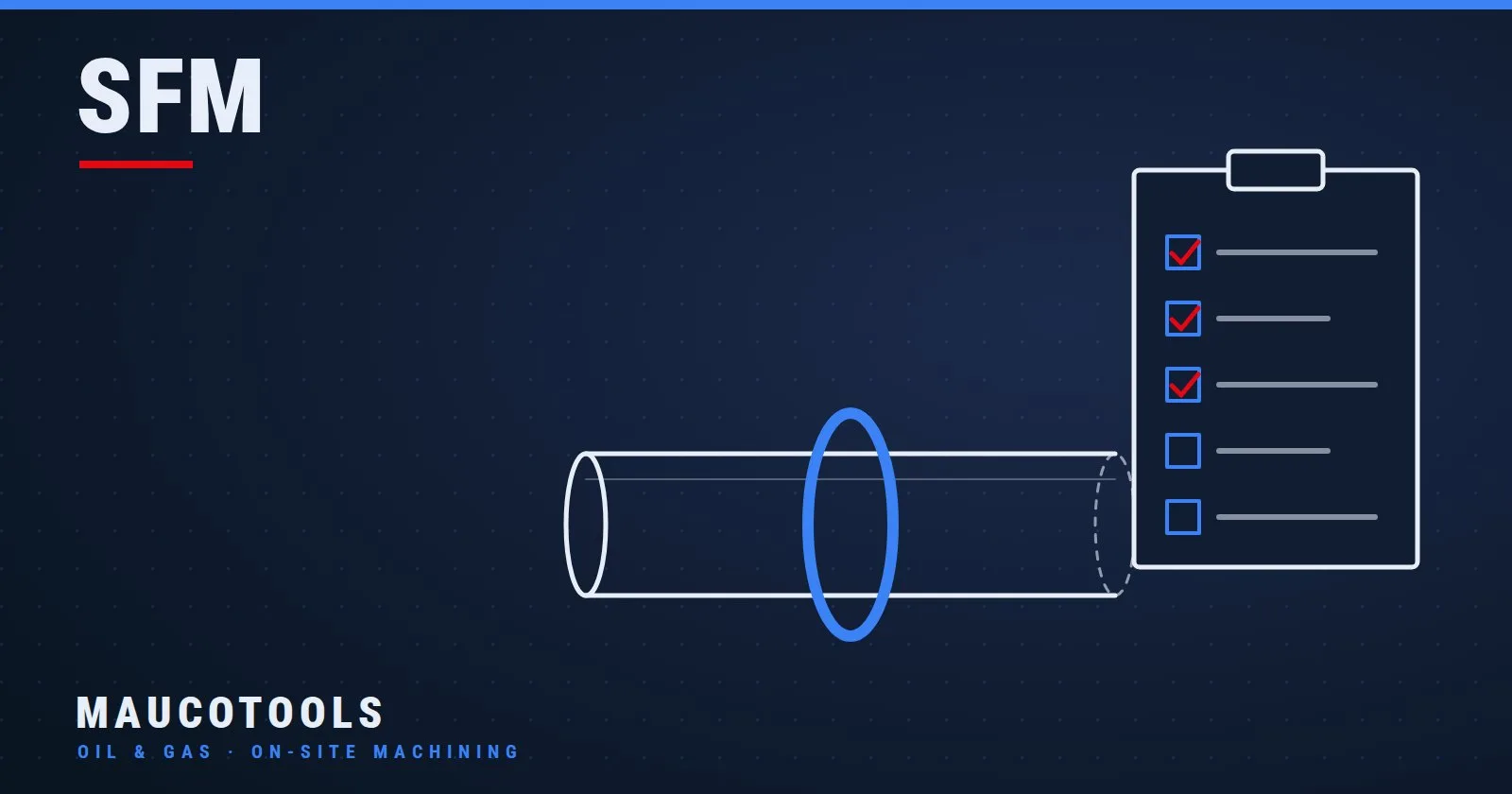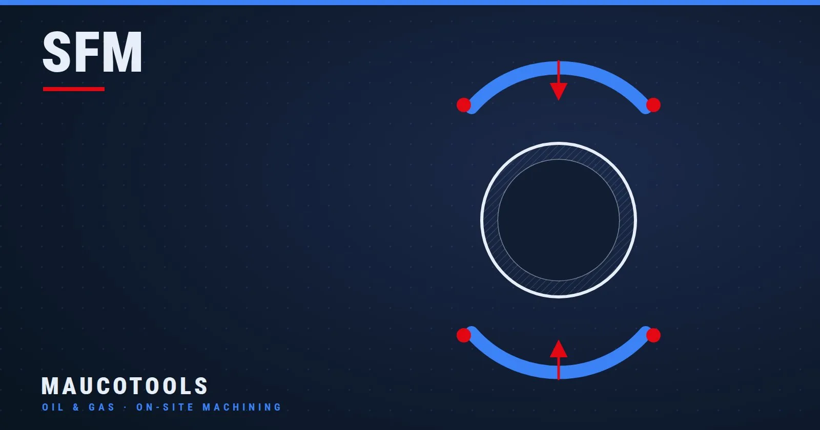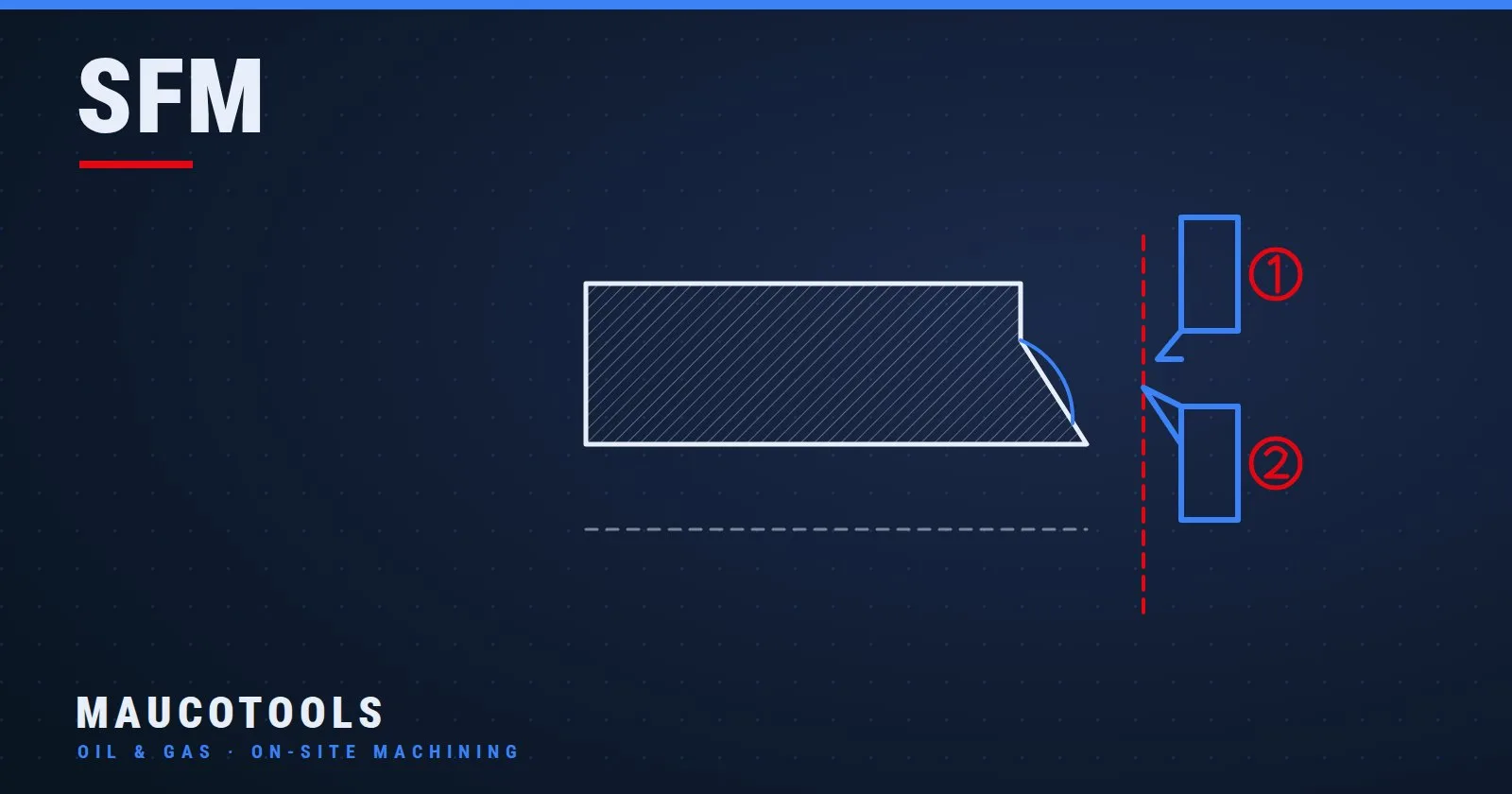
Line boring is the metal-cutting operation that brings an existing bore to its nominal diameter, holding tolerances down to H7 with surface finishes no twist drill can deliver. It is performed in the workshop on fixed boring mills, but also directly on-site with portable line boring machines, without dismantling the component.
Search for information on line boring and you will find the same explanation almost everywhere: a definition, the difference from drilling, a couple of lines about the tool. Useful, but incomplete. In real-world maintenance — an ovalized bushing on an excavator, a bearing seat out of spec on a turbine — the real question is not "what is line boring", but "how do I do it on a component I cannot bring back to the workshop".
This guide covers both: the fundamentals of the operation (tooling, parameters, tolerances) and the part that is usually missing — on-site line boring with portable machines, including the reclamation of worn bores by welding overlay followed by re-boring in the same work sequence.
To find your way around the range, see the guide on how to choose the right portable line boring machine.
What line boring is and when you need it
Line boring is a precision boring operation: a single-point cutting tool, mounted on a rotating boring bar, removes material from the inner wall of an existing bore to enlarge it to the required diameter, correcting cylindricity, coaxiality and surface finish at the same time.
The difference from related operations comes down to this:
Drilling: creates the hole from solid stock. Dimensional accuracy and finish are limited; the hole can wander off the theoretical axis.
Reaming: finishes a bore already very close to nominal size, removing just a few tenths of a millimetre. But a reamer follows the axis of the existing bore: it does not correct it.
Line boring: defines the working axis itself. The bar rotates on its own supports, so it can bring even an ovalized, tapered or misaligned bore back to size and back on axis.
It is this ability to correct geometry, not just enlarge, that makes line boring irreplaceable in two scenarios: the production of precision seats (bearings, bushings, H7 fits) and maintenance, where the bore does not need to be created but reclaimed after years of wear, seizures or out-of-tolerance clearances.
The typical cases a maintenance engineer runs into: pivot pins and bushings on excavator buckets and booms, bearing seats on hydroelectric turbines, hydraulic cylinder eyes, hinge points on presses and agricultural machinery, mounts on skids and Oil & Gas structures.
Tooling, machines and parameters: how it works in practice
The heart of the system is the boring bar: a ground shaft that passes through the bore to be machined, held by supports at either end, carrying the insert-type cutting tool. The bar receives two motions: rotation (the cutting motion) and axial feed. On every revolution the insert traces a helix and removes a chip whose thickness equals the feed rate.
The machines that drive these motions fall into two families:
Fixed workshop machines: boring mills, but also lathes and milling machines fitted with boring heads. Maximum rigidity and material-removal capacity; they do, however, require bringing the workpiece to the machine.
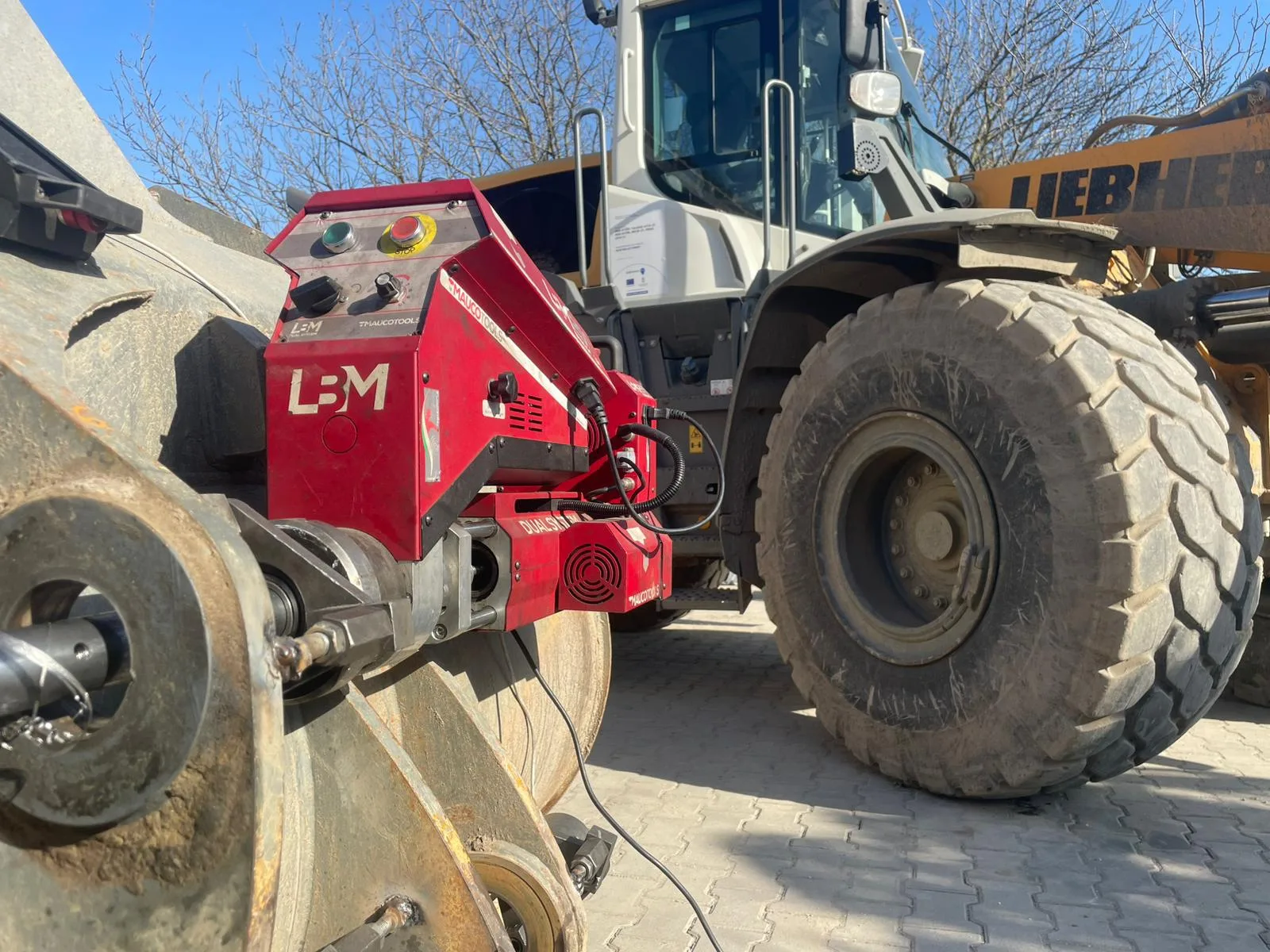
Portable line boring machines: the machine goes to the workpiece. The rotation and feed modules mount directly on the component, the bar is aligned to the theoretical axis of the bore, and machining takes place in situ. An LBM250 Dual System, for reference, performs line boring from Ø42 to 250 mm (1.7–9.8 in) with 20 and 40 mm bars, powered by a 1.8 kW electric or 5.5 kW hydraulic drive.
For cutting parameters, the usual rule applies: they depend on diameter, material and insert type. Some practical reference points to get the setup right:
Rotational speed: decreases as diameter grows, for a given insert cutting speed. Portable machines offer adjustable ranges for exactly this reason: the electric LBM250 runs between 54 and 126 RPM in first gear and between 180 and 423 RPM in second; the hydraulic version covers 9 to 423 RPM continuously.
Depth of cut: heavier roughing passes to remove the material, then light semi-finishing and finishing passes to hit size and surface roughness.
Feed rate: this is the parameter that governs finish. For bearing seats it is reduced on the final passes until the surface required by the fit is achieved.
With a correct setup and proper finishing passes, tolerances of class H7 — the typical standard required for bushing and bearing seats — are achievable even in situ.
Line boring in the workshop or on-site: how to choose
The choice is not ideological: it is a matter of logistics and the cost of machine downtime.
Workshop line boring remains the right route when the part can be removed and transported without penalty: new components in production, small parts, batch work. A fixed machine offers superior rigidity and productivity.
On-site line boring becomes the only option — or simply the more economical one — when dismantling costs more than machining:
The component is large, heavy or structural: an excavator boom, a press frame, a mount welded to a hull or steel structure.
Dismantling means days of plant downtime: a hydroelectric turbine, an Oil & Gas line, a lifting installation.
The site is far from an equipped workshop: round-trip transport plus external machining lead times add up to weeks.
The traditional method — shut down, dismantle, ship to the workshop, wait — loads the cost of days of machine downtime onto the reclamation of a single bushing. On-site machining flips the equation: a modular machine is brought to site, mounted on the component, and the work begins. To weigh up the economics for your own case, the Maucotools ROI calculator lines up downtime, transport and machining costs side by side. And to find out how much a portable line boring machine costs and what drives the price, there is a dedicated guide.
Then there is a point that generic content on line boring never touches: in maintenance, before you bore, you almost always have to rebuild. An ovalized bore cannot be reclaimed by removing material alone — it would end up oversize. The correct sequence is welding overlay on the worn surface followed by line boring back to nominal diameter. With Dual System technology, both operations are performed with the same machine and the same setup: no double positioning, no realignment errors between welding and boring, with setup times in the order of 14 minutes in documented cases. Whether a portable line boring and welding machine or a line boring machine plus a separate welder is the better buy depends on overlay frequency, diameters and job sites: the dedicated guide compares the two set-ups.
Which portable line boring machine for which job
For anyone assessing equipment, the main criterion is the diameter range of your fleet, followed by weight and mounting logistics:
LBM250 Dual System — working range Ø22–250 mm (0.9–9.8 in) (line boring 42–250 mm, drilling and tapping 10–45 mm, optional threading kit). Separate rotation and feed modules of around 17 kg (37 lb) each: a single operator can mount it even at height, and the split design allows simultaneous machining. It is the benchmark for earthmoving: buckets, booms, bushings, pivot joints.
LBM400 — Ø42–400 mm (1.7–15.7 in), for medium-heavy work as diameters grow.
START160 — Ø22–160 mm (0.9–6.3 in), a compact entry-level machine for those starting out with smaller-diameter jobs.
All of them work in situ; the LBM range adds integrated welding overlay following the Dual System scheme described above.
Common mistakes in on-site line boring (and how to avoid them)
The mistakes that ruin a line boring job almost always happen before the cutting starts. The most frequent:
Sloppy bar alignment. This is the cardinal error: if the bar axis does not coincide with the theoretical axis of the bore (or of the bore pair, for hinge points), you produce a perfect hole in the wrong place. Centring must be done off the component's functional references, not off the worn bore.
Boring without rebuilding. Taking a "clean-up" cut on an ovalized bore without overlay means going past nominal diameter and having to resort to non-standard oversize bushings. If the wear exceeds the available stock, weld first, then bore.
Double setup between overlay and boring. Removing the welding rig and mounting the boring rig introduces a fresh alignment error. Machines that perform both phases with the same setup eliminate the problem at the root.
An undersized bar or supports set too far apart. Bar deflection produces taper and vibration: use the largest bar diameter the bore allows, with supports as close as possible to the cutting zone.
Finishing with roughing parameters. A light final pass, reduced feed, an insert in good condition: that is where an H7 fit is won or lost.
Measuring while the part is hot. After welding overlay the material is thermally expanded: final dimensional checks must be made at stabilized temperature.
Step-by-step procedure: reclaiming a bore in situ
The typical work sequence for a line boring and overlay job on an in-service component — say, a pivot joint on an excavator boom:
Inspection and measurement. Measure the worn bore (ovality, taper), check the nominal diameter on the drawing and the required alignment with any coaxial bores.
Mounting the supports and the bar. The supports are fixed to the component (normally by welding on mounting plates or using dedicated fixtures); the bar is inserted through the bore and set to rotate freely.
Centring. Align the bar to the theoretical axis with a dial indicator, working off the functional references. This is the phase that determines the quality of the entire job.
Pre-boring clean-up cut. A light pass to bring the bore back to cylindrical and expose sound material, ready for the overlay.
Welding overlay. With the welding head mounted on the same bar, the overlay is deposited in a spiral on the inner surface, uniformly and under control. On an LBM250, internal overlay covers diameters from 32 to 250 mm, external from 22 to 250 mm.
Boring to size. Rough out the overlay, then semi-finish and finish to nominal diameter within the required tolerance.
Final inspection. Dimensional and geometric checks at stabilized temperature, plus a trial fit of the pin or bushing.
A real-world reference for this sequence: the reclamation of the pins on a Caterpillar 307.5 bucket carried out by Officina Mobile Torsani with an LBM250 — line boring and welding overlay in situ, H7 tolerances restored without taking the bucket to a workshop. The full details are in the dedicated case study; the topic of reclaiming pins without dismantling is also covered in depth in our article on restoring excavator pin tolerances on-site.
Line boring FAQ
What is the difference between line boring and reaming?
In shop-floor language the two terms often get blurred. Strictly speaking, reaming finishes a bore that is already close to size, following its existing axis; line boring uses a single-point tool on a rotating bar and defines the working axis itself, so it also corrects ovalized or misaligned bores. Line boring is, in effect, precision boring with the ability to correct geometry.
What tolerances can be achieved with on-site line boring?
With a rigid machine, a properly supported bar and adequate finishing passes, tolerances down to H7 are achievable — the typical class for bushing and bearing seats. The result depends on the setup: centring, bar rigidity and the parameters of the final pass matter more than machine power.
Can a heavily worn bore be line bored without welding overlay?
Only if the wear falls within the stock available before reaching nominal diameter, which is rare on ovalized bores. In all other cases the correct sequence is welding overlay followed by boring to size: with Dual System machines both phases are performed with a single setup.
How long does it take to set up a portable line boring machine?
It depends on bore accessibility and the fixturing system. As an order of magnitude, in the documented case study with the LBM250 the setup took around 14 minutes; the most delicate part remains centring the bar, where cutting corners never pays.
When does on-site line boring make more sense than the workshop?
When the cost of dismantling, transport and machine downtime exceeds the cost of the on-site job: large or structural components, plants that cannot stand still for long, remote sites. For small, transportable, batch-produced parts, the workshop remains the more efficient choice.
Line boring is an operation built on fundamentals: axis, rigidity, parameters, measurement. What has changed is where it can be done. With portable line boring machines, the old constraint that "boring only happens in the workshop" no longer exists: bushings, pivot joints and bearing seats can be rebuilt and brought back into tolerance right on the job site, with the machine mounted on the component.
To find out whether a specific job falls within the capabilities of a portable machine — diameters, overlay, accessibility — the starting point is the LBM250 Dual System product page or a call to Maucotools technical support.
Welding overlay and work at height require qualified personnel: always operate in compliance with applicable safety regulations and the manufacturer's instructions.