The weld bevel is the machining of the pipe ends that creates the groove into which the weld pool penetrates down to the root. With a portable ID-mount pipe beveling machine the bevel geometry is concentric to the pipe axis and repeatable on every joint, with no flame and no heat-affected zone. Bevel angle, root face and root gap stay exactly as the WPS defines them.
In petrochemical piping, in power plants, in shipbuilding or on heat exchangers, the welded joint is the point that passes or fails radiographic inspection. Most root defects originate before the arc is struck, in the preparation of the pipe ends.
What a weld bevel is and why it decides joint quality
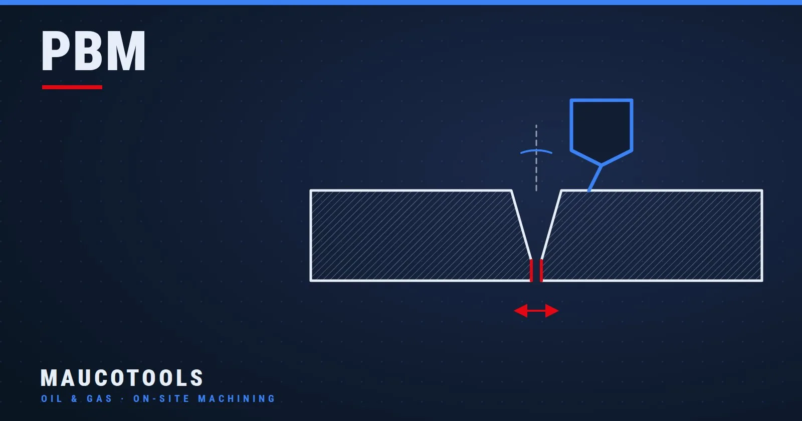
The weld bevel is the chamfer machined on the end of the pipe so that the two abutting ends form a groove of defined cross-section. In that groove the welder lays the root pass and then the fill and cap passes. Without a bevel, as soon as the wall thickness exceeds what the arc can fuse in a single pass, the weld does not reach the bottom of the joint.
Bevel geometry is described by four quantities:
- Bevel angle: the inclination of the chamfered surface relative to the plane perpendicular to the pipe axis. Two abutting ends form the groove angle of the joint.
- Root face (land): the portion of wall thickness left flat at the pipe end, which supports the root pass and governs its fusion.
- Root gap (root opening): the clearance between the two root faces at tack welding, which lets the weld pool penetrate through to the inside surface.
- Alignment: the coaxiality of the two pipes and the matching of the walls on the inside surface; any misalignment leaves a step at the root that no weld pass can recover.
The most common geometries are the V-bevel, with straight faces, and the J-bevel or compound bevel, with a radius blending into the root face and a reduced angle on the outer part, used on heavy wall thicknesses to reduce the amount of weld metal deposited. The figures that circulate in the shop, such as 30° per side on a V-groove or 37.5° on typical piping preparations, are generic examples: the binding value is set by the WPS (Welding Procedure Specification) for the joint, together with root face, root gap and welding process.
Every deviation is paid for in welding or at inspection: too narrow an angle and the root is not reached; an uneven root face and the root burns through where it is thin and fails to fuse where it is thick; a face that is not square and the gap varies around the joint. On radiographed joints this means gouging, re-welding and a new inspection, with the line standing idle.
Grinder and oxy-cutting versus beveling machine: what changes on the joint
Preparing a bevel with an angle grinder is possible and many shops still do it. The limit is not the pipefitter's skill, it is repeatability: the angle depends on the hand, the root face is left by eye, the squareness of the face is corrected by trial and error. On a small-diameter, thin-wall pipe it may be enough; on a line with extensive radiographic inspection, it is not.
Oxy-cutting or angled plasma cutting are fast but leave a heat-affected zone, oxides and a surface that has to be ground anyway before welding. On stainless steels, duplex and nickel alloys, flame preparation is normally excluded by the procedures precisely because of the metallurgical alteration of the pipe end.
An ID-mount beveling machine works by chip removal with fixed-geometry tools. The result has three properties that cannot be achieved by hand: the angle is that of the tool and does not change around the circumference; the root face is flat and constant because the facing cut is concentric to the axis; the surface is metallically clean, with no oxides and no heating.
The grinder remains reasonable for touch-ups and occasional repairs on non-critical pipes; from process piping to heat-exchanger tube bundles, machine preparation is the rule.
How an ID-mount beveling machine works
A portable ID-mount pipe beveller (ID Locking) is a machine that anchors itself inside the pipe by means of an expanding mandrel and machines the pipe end with a rotating tool head. The mandrel, inserted into the pipe bore, expands its expanders until they clamp against the wall: from that moment the machine axis coincides with the pipe axis.
This is what makes the geometry concentric: the head rotates around the same axis on which the pipe has been centred, and the axial feed brings the tools into the material at a uniform depth along the whole circumference. The head carries several tools at once: one for the bevel, one for facing the pipe end to generate the root face, and on request optional heads for the outside bevel or for weld bead removal.
The Maucotools PBM series is available in electric, pneumatic and hydraulic versions; the smallest model, the PBM-1625, also comes with an 18 V Li-ion battery and with a lever feed. For the PBM-1625 the catalogue states a setup time of under 2 minutes thanks to the ID locking.
When the pipe has no free end into which the mandrel can be inserted, for example on an installed line that has to be cut into sections, the right machine changes: you move to an SFM split-frame pipe cutting machine, which mounts on the outside diameter and cuts and bevels in a single operation.
Choosing the PBM beveller by inside diameter, material and power source
The first parameter is not the nominal pipe size but the actual inside diameter, because that is where the mandrel has to expand. The same NPS, with different schedules, has different inside diameters. ID clamping ranges of the PBM series models:
- PBM-1625: 20–42 mm (lever-feed version 12.5–42 mm)
- PBM-3000: 28–76 mm
- PBM-4000: 33–108 mm
- PBM-4500: 39–114 mm
- PBM-8000: 49–203 mm
- PBM-12000: 100–306 mm
- PBM-18000: 102–457 mm
- PBM-24000: 180–609 mm
Rule of thumb: work with margin inside the range. At the lower limit the expanders have minimal travel and clamping is uncertain; at the upper limit the machine works at maximum overhang and rigidity drops. The PBM-4000, clamping from 33 to 108 mm, with 143 Nm of torque and 10 kg (22 lb) in the electric version, is the typical mid-range model for small and medium-diameter process piping.
Material and wall thickness decide the torque and rigidity required. Carbon steel and stainless steel can be machined with the whole range; duplex, super duplex, Inconel and nickel alloys work-harden and resist cutting, and call for a machine that does not slow down under load. For the same diameter, on these materials and on heavy walls the model with more torque is the better choice, at the cost of a few extra kilograms.
The power source is chosen on the site. Electric where mains power or a generator is available; pneumatic where compressed air is already on the plant or where the atmosphere rules out electric motors; hydraulic on large diameters and where constant torque is needed continuously; Li-ion on small joints at height or in confined spaces, with no cables. For a one-off contract or a peak in workload, hiring the beveling machine for the duration of the job, sized on the work to be done, is often the more sensible option.
To compare power, torque and weight of every version, the PBM portable pipe bevellers page brings together the datasheets of the whole series; the Maucotools configurator helps you put together machine, heads and tools starting from the inside diameter and the material.
Large diameters and pipelines
From 49 mm inside diameter upwards the PBM-8000, PBM-12000, PBM-18000 and PBM-24000 models come into play, reaching up to 609 mm. Torque, power and mass grow with the diameter: the PBM-8000 weighs 22 kg (48.5 lb) in the electric version, the PBM-12000 reaches 44 kg (97 lb) with a 2000 W motor, the PBM-18000 90 kg (198 lb) with 1182 Nm, the PBM-24000 250 kg (551 lb) with 1400 Nm and 2600 W. Up to the PBM-8000 the machine is positioned by a single operator; on the larger sizes handling has to be organised with a hoist or a support.
Step-by-step procedure for preparing the weld bevel
- Measure the inside diameter on two perpendicular axes and check the ovality: if it exceeds what the specification allows, the pipe end must be restored or the pipe rejected. Compare the value with the machine's range.
- Clean the inside of the pipe in the area where the expanders grip: rust, mill scale, oil and cutting residues compromise clamping and centring.
- Select mandrel and expanders suited to the measured inside diameter, according to the manufacturer's tables, and fit them to the machine.
- Insert the mandrel to the specified depth and tighten the expanders progressively, checking that the machine is coaxial: an asymmetric clamp shows up immediately as wobble of the head.
- Fit the tools: the bevel tool with the angle required by the WPS and the facing tool. Check that the cutting edges are intact and the clamping screws correctly tightened.
- Zero the head by bringing the tools to just touch the pipe face and set the feed travel.
- Rough out with a constant feed, leaving stock for finishing; on duplex and nickel alloys keep the cut continuous, without stopping the tool in the material.
- Finish the bevel and face the pipe end until the root face reaches the required dimension, uniform around the whole circumference.
- Inspect with a bevel gauge or a template: angle, root face width at several points, squareness of the face to the axis. Correct before releasing the machine.
- Deburr and clean: remove internal and external burrs, degrease the pipe ends for the distance required by the procedure and protect them if welding is not immediate.
Common mistakes in pipe beveling
- Pipe not cleaned internally. The expanders clamp on mill scale or rust, the mandrel slips during cutting and the bevel comes out eccentric.
- Clamping at the limit of the range. With the expanders at the end of their travel the grip is weak and the machine vibrates; at maximum overhang the tool leaves a wavy surface. Choose the model, or the mandrel, with margin.
- Ovality not checked. On an oval pipe the mandrel centres on an average axis and the root face comes out wider on one side and narrower on the other.
- Angle different from the WPS. A tool with the usual angle instead of the one in the procedure: the bevel looks right, the weld inspection does not.
- Uneven root face. Facing skipped or incomplete: the root face follows the original pipe cut, often out of square, and the root pass becomes unpredictable.
- Worn tool. A worn cutting edge tears, heats and leaves burrs; on stainless and duplex it work-hardens the pipe end.
- Dimensional check skipped. One badly tightened expander is enough to ruin a joint that looked perfect.
Frequently asked questions
What is the typical bevel angle for pipe welding?
The bevel angle is defined by the WPS for the joint, as a function of material, wall thickness, welding process and position. Values such as 30° per side on a V-groove or 37.5° on typical piping preparations are widespread examples, not rules: read the procedure before fitting the tool.
What is the root face of a bevel and what is it for?
The root face, or land, is the flat portion left on the pipe end below the inclined surface of the bevel. It supports the weld pool of the root pass: if it is too thin the root burns through, if it is too thick it does not fuse. It must be uniform around the whole circumference: that is why machine facing of the pipe end is decisive.
Can stainless steel, duplex and Inconel pipes be bevelled with a portable beveller?
Yes, and machining is the preferred preparation on these materials, because it avoids the heat-affected zone of the flame. Duplex, super duplex, Inconel and nickel alloys work-harden and resist cutting: you need sufficient torque, intact tools and a continuous cut. The model is chosen with a torque margin over what would be enough for carbon steel.
How is a weld bevel checked before welding?
With a bevel gauge or a template cut to the WPS angle you check the angle, the root face width at several points around the circumference and the squareness of the face to the pipe axis. You then check that the pipe ends are free of burrs, oxides and grease. The check is done with the machine still clamped, so a touch-up does not require re-centring.
Can a bevel be re-cut on a joint that has already been welded?
Yes. If the joint has to be redone, the pipe is cut behind the weld and a new bevel is prepared; if a weld bead or weld residue has to be removed to restore a pipe end, the optional bead-removal heads fitted to the ID-mount beveller machine down to the base metal and re-prepare the end, again concentric to the pipe axis.
The weld bevel is the part of the weld that is decided before the arc is struck. An ID-mount beveling machine, chosen with margin on inside diameter and torque, makes the preparation repeatable, verifiable and free of thermal alteration, with fewer joints to repair.
To identify the model suited to the inside diameter and material of your line, the full range is on the PBM portable pipe bevelling machines page, from which you can request a quotation or a technical comparison between versions.
End preparation and welding must be carried out in compliance with the applicable safety regulations, the machine manufacturer's instructions and the required PPE; the pipe must be secured and stable before starting the machining.